Tuesday, 1 October 2024

Experiments in tube drawing

 We plan to make a new radiator to the original pattern for our 1916 fire engine. 

This is a slightly unusual design consisting of vertical stadium shaped tubes (3/4 inch by about 3/32) arranged in fives front-to-back and then with corrugated sheets between them to brace and add surface area. 

We pulled out a section of the original tube and it turned out to be about 0.2mm thick (36 swg?) and to our surprise it had clearly been folded out of brass sheet with a soldered seam. 

Asking a radiator specialist, this is apparently "lock seam tube" and not currently favoured. 


After a bit of CAD measurement it seems that the ideal tube to reproduce this would be 13.5 mm diameter, which isn't a readily-available size, especially not in 0,2mm wall thickness. 
However 17/32 x 1/32 tube is readily available from model shops as part of the K&S range of telescoping imperial tube. Readily available, but nit very cheap at £6 for a 12" length. 

I decided to start experimenting with this, and was slightly stumped on how to machine them until it occurred to me to split the die. I CNC milled them into some silver steel. 


I managed to hammer some tube far enough through the die to get started, then spent ages trying to think of ways to hold the end and to pull hard enough to draw it. I didn't want to go too far down the rabbit hole of making draw benches and specialised grippers until I knew whether it looked plausible and had some idea what forces were likely to be involved. 

Eventually I had the idea of just silver-soldering my swaged and crumpled bit of tube into a slot in the end of some threaded rod. 


Then I could use some bits of scrap tube, redundant parts etc to make a the Pugh Super Janky Drawbench™ 


As expected by several of us, the tube collapses into a figure of 8 shape. 
Which would work, but isn't what we were after. I think that this is possibly solvable with a floating mandrel, though. 


Anyway the main purpose of this test was to prove that we have the capability to make the tooling and to measure the drawing force required. 
Using a luggage scale on the end of a 19mm spanner I measured 3kg @ 21cm, or close enough to 6Nm. 
Using an online bolt calculator that suggest a tension force of 2.5kN to pull the tube through the die. 
So I will use that as the basis for the drawbench design.  This falls inside the normal working load of bicycle chain, so that will probably be the operating mechanism used, at least initially. 

According to the internet:
"for a standing person operating a rotating wheel or crank arm - the length of the arm (or radius of the wheel) should be approximately 0.4 m and maximum force should not exceed 130 N"

So that suggests a working radius at the sprocket of 20mm, which matches a 10 tooth sprocket. 
This is smaller than I would really like to be using, so there may be a need for a primary reduction. 

Thursday, 3 May 2018

Assembly instructions for the STMBL Servo Drive

The STMBL is an open-source 3-phase servo drive suitable for motors up to 2.2kW. Further details can be found here

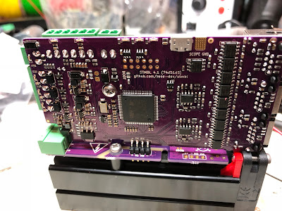
I had a batch of 50 PCBs made by PCBAStore for a very reasonable £47 per board. These kits were without the more bulky and expensive components. This blog post describes how to assemble one of the kits in to a working drive.

The main documentation (work in progress) is relevant to both the current and future versions of the drive. However due to the withdrawal from the market of the IRAM256 chip used by the board any future versions are likely to be physically different and assembled differently which is why this is a blog post and not a documentation section.

1) Test the board and flash the firmware.
There is no point assembling the board if it is a dud. The boards are supplied with the two halves linked and with a bridge that permits communications.
Before the boards are powered up they need to have C143 (22µF 6.3mm dia)  installed. Most of the boards that I supply will have this already. Do not power up the boards without this component.


Ensure that the white stripe on the capacitor is adjacent to the corresponding stripe on the board silkscreen. 

The board can then be powered up with 24V to both halves. There should be two green LEDs illuminated 
This is a good time to flash the firmware. See the main documentation for instructions how to do this. 


Once the firmware is flashed and the basic functionality of the board is assured the larger components can be added. C21 and C22 (270µF 400 / 450V) should be added first. Again make sure that the stripes line up as shown below. Trim the leads off short to ensure spacing from the IRAM module. 


It is imperative that the screws have insulated washers. These are supplied with the kit. Their function is to retain isolation gaps between the screws and the board tracks. 


The IRAM module is spaced from the PCB with special 3D printed standoffs. It is easier to fit these round the screws (M3 x 14mm) prior to intalling the IRAM256. 


 Thread the IRAM256 into the PCB holes and on to the standoffs.


Screw the mounting screws in to the threaded holes on the heat-sink. A dab of heat-sink compound will not come amiss at this point. 

Add a plain standoff and another screw. The slots in the extrusion are grooved to accept M3 screws, so this will get a decent grip. 


The IRAM256 can now be soldered. Take care to ensure that solder flows all the way through to join the tracks on both sides of the board, as shown below. These are high-current connections and relying on the through-hole plating to link the board-sides is not a good idea. 


The 3D printed fan-mounts can now be installed. 


And the fan can be fitted. The 3D-printed parts ensure that the fan is at the right height for later. The lower screws seem able to make their own threads in the lower grooves of the heatsink. 
The photo shows the fan fitted the wrong way round, it should blow-in not suck-out. 


The right-angle header should now be fitted, in the orientation shown, and on the side of the board shown. 


And the steady-bracket can be fitted with the self-tapping screw provided. 


The vertical board is designed to sit hard down on the fan and on the connector block. In this position and with the capacitor bracket it is really quite strongly and rigidly supported. It is important to solder the header in-situ to achieve this. 


Connect the fan wires and the drive is completed. There are two schools of thought on fan wire routing, some prefer the wires to start from the other corner and connect on the other side of the PCB.


Friday, 30 March 2018

Rebuilding the Harrison Milling Machine Vertical Head

My little Harrison Milling Machine has a vertical head adaptor that takes power from the horizontal spindle, converting it into a conventional vertical milling machine. There was a version of this with step-up gearing but mine has the 1:1 version so my maximum speed is a rather lowly 1000rpm. (Though the VFD allows me to push this to 1400)


Unlike most of this model of milling machine mine is CNC and has a pneumatic power drawbar. But the vertical head is unmodified so the following should apply to all of them.

When I first got my mill I found that oil leaked out of the bottom bearing cover. I took it off and found no oil seal, so I added one assuming that Harrison were relying on the grease in the bottom bearing cover to keep the oil in the bevel box in.
Taking the head apart I realised that this was a misapprehension on my part,  and that Harrison did actually know what they were doing. There is a sleeve fixed into the bottom of the casting which reaches up inside to above the oil level, and then a cup on the spindle shaft that comes down to below the top of this sleeve to stop oil falling in. The only way for oil to get in to the bottom bearing is if the oil level is set considerably too high. It seems likely that grease from the bearings will end up in the oil, though, after a few years of fills.

I had not been planning to take mine apart, despite the fact that it was very noisy. leading to concerns about the very expensive bearings. However after adding oil to the primary drive gear area it suddenly started to make a regular tapping/knocking noise so I decided to see what might be wrong.

The first thing to do is to remove the vertical head. It is a heavy and unwieldy device so it probably makes sense to start disassembling with it still mounted on the machine.

There are two oil spaces in the head, one for the step-up gears and one for the bevel box. There is a drain screw in the bottom of the rear casting for the former. The easiest way to drain the top is probably to remove the inspection cover on the right (5 Allen screws under the lubricant label) and then rotate the head through 90 degrees.

This would be a good time to loosen the screws on the bearing covers.

With the bevel drive drained it can be easily removed from the rear casting by removing the nuts from the 3 T-bolts and simply drawing it forward.
The T-bolts can be removed through the hole that is left when the top-hat bush around the zero-degree angle locking taper pin is removed. This is retained by a small grub screw.

The bevel bearing assembly itself can then be removed from the main body. It is retained by a number of socket screws.

There are two threaded jacking holes to help pull this assembly out. Two of the screws from the top bearing cover have the correct thread and can be used.


The bevel support housing will have been shimmed. Mine had two plastic shims, as shown below. 


A document that I found online says that bevel gears will have markings to say the correct offsets from the mating axis and backlash, but I could not find any such markings on these gears. I just had to assume that the existing shims were correct. I did not dismantle this assembly. 
Note the three oil-drain holes in the main housing. These should be at the bottom when the housing is reinstalled. 

Removing the spindle begins with removing the top nut and washer. It has three locking grub screws that bear on to the thread. Hopefully this hasn't damaged the thread too much (it hadn't on mine)

The spindle is a very tight fit in the top bearing inner race. In fact on mine it was too tight for the adjusting ring to move. There is no "nice" way to push it out without reacting the force against the top bearing. I ended up using an aluminium drift and a big hammer. A press would have been nicer.

To remove the spindle it is necessary to progressively unscrew and slide a number of parts off of the spindle. Starting at the top there is a collar above the bevel gear, then the gear, then a spacer and then the combined oil control cup and adjuster. The upper ring and cup adjuster also have three locking grub screws each. 


I was stumped for a little while about the drive key for the bearing, and how to get it out to allow the spacer and adjuster to pass. Eventually I realised that both the spacer and the adjuster have a keyway slot, so they can slide past. The adjuster comes off of its threads before it hits the key. 


This picture shows the oil-control sleeve which stops the oil falling out through the bottom spindle bearing:


With a bit of a fiddle and some carefully-applied brute force the spindle was removed. 


The inner race was not removed. I don't know how you would, but it might well be possible to push it off using the 4 threaded holes in the 30-INT mounting face. These must be through-holes as the grease comes out through them. 

The inner and outer bearing races and the cage are held together by snap-rings (by a nylon ring on the bottom and a wire ring on the top in my case)
The bearings are a bit fancy, with hand-engraved ID etc. 


The internal baffles top and bottom would make bearing replacement a bit of a game. However there is space underneath the race for a hook-shaped puller of some sort. The baffles seem to be held in with small grub-screws radially onto their edge. 

I took the rollers out to clean them. They all have a hole right through the middle (for cooling in oil-lubricated situations maybe?). The rollers are subtly tapered, it would probably be a bad idea to get one the wrong way round. In the picture below the one highest in the frame is small-end up, the rest are big-end up. 


After a clean and re-grease of the bearings assembly was the reverse of disassembly. 


A spanner on the drive dogs can be used for holding the spindle while the various rings are tightened. 
I am using a punch here, but a modified C-spanner from an ER20 collet set was better for final tightening. 


The document on bevel gears that I linked to above says that the gears should be set to the backlash engraved on the gears. Mine had no such number, so I had to guess. But I did measure it. 


The primary drive gear assembly presents no special problems, except for one, and I forgot to take any photos. 
The gear and 30INT adaptor arbor, along with the oil seal cup can be removed as a unit once the oil control baffle is removed. This is located only by a grub-screw on the operators-right of the machine. 
It presses radially onto the baffle. With this loosened the baffle plate and the gears / shaft can be removed. There are tapped holes in the baffle plate, probably for a puller. But I found that I could remove mine using the gear/shaft as a slide-hammer to gradually work it out. 
There is an O-ring around the baffle, but mine was completely flattened. I may source a new one at some point, especially if leaks turn out to be an issue. 

I found that the drive-dog area on my spindle adaptor was fatigue cracked and had parts missing on both sides. I made a new input shaft out of a 30-INT to No 5 Jacobs Taper adaptor (The No5 Jacobs taper is _huge_). 

For reference the bearings are listed in the parts book as:
355X / 345B bottom spindle bearing - Simply Bearings used to have these at £275 but not any more.
28137 / 28315B top spindle bearing (£243. They also have a Gamet bearing with the same OD and ID but it is deeper and that would be a problem)
28150 / 28315B (x2) bevel carrier bearings. (£121)
These bearings have flanges on the outer race and fit into plain bores in the castings.


Tuesday, 20 March 2018

LED Headlight Conversion

I fitted HID lights to my R1 soon after I got it. But I have never really been happy with the main beam performance. (Fine when warmed up, but takes a long time to get there) and also I have always ended up with miss-matched colour temperatures after one failed.
I then read a document saying that the MoT test rules were going to get more strict on aftermarket HID,  and with the MoT test imminent I decided to swap to LED lights. (Mainly because they swap out for halogens a lot more easily)

I did a tiny amount of research online and bought some of these based on an online recommendation of another (US Amazon only) lamp with the same LED.
https://www.amazon.co.uk/gp/product/B078YRBNM2/

Somewhat later I read this rather informative blog post with actual measurements and tests
https://www.autobulbsdirect.co.uk/blog/are-led-headlight-bulbs-the-brightest/

Had I read that first I probably wouldn't have bought the ones I bought.

Anyway, fitting them was pretty easy, once I had removed the HID bulbs and their ballasts. (Which was less easy, I had fitted them rather "elaborately" all those years ago.)

With the new bulbs in place there was a slight problem:


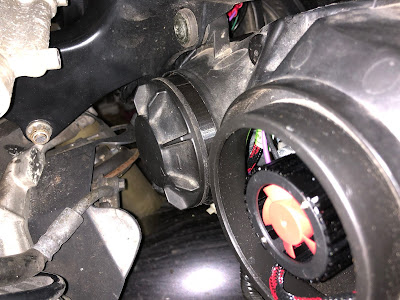
As can be seen, the fan/heatsink pokes rather a long way out of the back of the dipped beams (though not out of the main beams to any great extent).

The solution was simple, and for pretty much the first time my 3D printer was set to work making actual working parts (It has made quite a few foundry patterns).


This is what the part looks like, it is a copy of the bayonet of the original rear cover, mated to a copy of the socket of the headlamp unit. 


It looks reasonably tidy in-situ. 


The main beam units originally have a rubber cover with a hole in it for the lamp connector (I have no idea why they fitted a neat cover to the dips and an old-fashioned thing to the mains.
I need to mention here that a side-effect of the funny rubber cover is that the main bulbs need a plug-on adaptor that pokes through the rubber. The spring clip for the bulbs won't work without this, or some other spacer. I used some that I machined from Delrin for the HID elements. It might be possible to cut-down the original spacers but making something is probably better, and it could be done with a hacksaw and drill if some plastic rod of the right diameter was located. 
I had some spare dip-beam back covers as a side-effect of a high-side at Cadwell Park and made some adaptors to allow those to mount to the main beam housings. 


The place where the rubber cover mounted is tapered, so I modelled a matching taper on the new part. It just pushes on and sticks like a Morose Tapir Morse Taper. I might add glue later. 
Unfortunately because the bayonet latches of the covers won't fit through the rim on the housing these adaptors end up a bit long. 
I hope that I will eventually get used to the aesthetics. If not I might have to try something else. I could just glue the cap into the adaptor and rely entirely on the taper, that would shorten the assembly significantly. 

At least there is plenty of space for air circulation. 


I did end up removing one fin from the dip beam cover. The bottom yoke _just_ touched it at full lock,  and I know how much the MoT man hates that sort of thing. The main beam covers are a long way below the bars at full lock and are no problem at all. 


Monday, 29 May 2017

Magneto Recharger / Remagnetiser for flywheel magnetos.

Much to my chagrin, the Ner-a-Car has not actually run since I took it on a trip to France. I have occasionally had an idea, tried it (replacing the capacitor with a modern one, for example) failed to make the bike run, and given up.
With a vintage vehicle day at work, and the Banbury Run looming in the near future I decided it was time to consider the bike again.
The spark seems very weak, and it wasn't all that weak before, so I wondered if perhaps the magnets had lost their magnetism. There isn't really much reason for them to, and I had them re-magnetised during the rebuild, but I speculated that perhaps the bike had been parked for a long time without the magneto armature being in the right place to act as a keeper. (it's a 2-stroke single, there are not many things that are capable of stopping it working).

Lots of people have build magneto chargers before, but nearly always for the usual horseshoe-shaped magnets that are found round the outside of the typical unit magnetos. The Ner-a-Car has the magneto magnets as part of the flywheel, which apart from anything else means that the magnetiser needs a bigger than normal span.
Initially I was planning to make a magnetiser almost exactly the same shape as the magneto armature, but after thinking it through I decided that a conventional layout would work, and would be adaptable for other types.

It seems to be agreed that you need 20,000 Ampere-turns to remagnetise a magneto. I did some calculations in Excel during my lunch-hour. I attempted to optimise for the minimum mass of wire.
I figured out some numbers and bought 1kg of 1mm wire and then waited for it to arrive. I then realised that I had made an error in my calculations, and had been under-estimating resistance by a factor of 10. This meant that my 20A 240V coil would actually be a 200A coil, and that seemed like a bad idea.
So, I had a bit of a re-think and decided that I would use 2 x 12V coils in parallel. These would take 60A, but anyone with a vehicle that doesn't rely on a magneto and generator has a suitable supply in the form of the battery.

So, I ordered 1kg of 1.4 mm (diameter) wire.
The coil formers are 25.4mm mild steel bars, machined to a length of 86.5mm with 5mm plastic end-caps pressed on. The windings are 7 layers of wire @ 50 turns per layer for a total of 350 turns per coil. 30A through each coil is 21,000 Ampere-Turns.
The coils are linked and mounted by a mild-steel bar, 35 x 20mm. I made some top pieces out of the remainder and the thing is assembled with M8 screws.

When I wound the magneto itself there were 20,000 turns to wind, and I did it on the lathe under power. However this wire was a lot stiffer, and was going to need more attention to persuade it to lie straight, so I mounted the bars on a threaded stub in the chuck of my Rivett lathe, and mounted a winding handle on the other end. Then I wound the coils by hand with the lathe drive disconnected.

The wire terminates at 1/4" copper tags fitted into slots machined in the end-caps and secured by an M2 countersunk screw. One end of the wire was filed clean of varnish and tinned, then soldered to the tag. Then the assembly was carried down to the lathe, mounted and wound. At the end of layer 7 the wire was cut, tinned and soldered to the other terminal tag.

I didn't take any photos of the construction. In fact I didn't take any photos until I had finished.

Once assembled I used a small current-limited PSU to identify the N and S poles, using a device that I got from eBay.  testing with my magneto (which has a clearly stamped "N" on one pole I was able to determine that with my pole finder the red end points to N.

Something that hadn't been 100% clear to me prior to building this device is that when magnetising a magneto the N of the magneto magnet sits on the S of the charger. (which I think is somewhat the reverse of the situation with a battery charger)


The magneto is simply placed on top of the charger and the other ends of the wires held against the battery terminals for a few seconds. The coils became warm but not hot in that time-scale. 


Did it work? I am not 100% sure. But I did get to ride the bike round the block early this afternoon. 


Tuesday, 23 May 2017

Harmonic Drive 4th Axis

I have already made a 4th axis for my cnc-converted Harrison Milling machine. It is a servo-driven BS0 dividing head. It works OK but lacks the torque for 4th-axis milling and it is impossible to have the backlash low enough in the sloppy bits without the servo stalling in the tight bits. It still makes gears relatively OK, but you can almost forget rotary-axis engraving.

I found out that Harmonic Drive make some really nice integrated drive/bearing/servo assemblies that are pretty much a 4th-axis waiting to happen. Lots of torque capacity, a large crossed-roller bearing and an integrated servo drive with a hollow shaft for through-spindle work. All very nice, and extremely expensive new. They are even expensive on eBay, but if you set up a watch you can occasionally find a bargain. I was in no hurry, and eventually picked one up for $250 from a seller in the US. It wasn't quite that simple, I had to get it shipped to a friend in Richmond, CA, then he stripped off a huge and heavy bracket and sent it on the slow (and cheap) boat to me. I ended up paying both California VAT and UK VAT on it, but it still saved a few $100 on the original quoted shipping price.

The drive I got was an older FHA-25B drive. This turned out to be a happy accident, as the FHA-xxB drives use Hall sensors for commutation and conventional quadrature encoders. The later FHA-xxC drives use a proprietary serial encoder for feedback and commutation, and only really work with the dedicated drives. If you choose to follow this route, look for the B-series actuators. 

The harmonic drive is pretty-much ready to go as-is, it just needs a bracket. I decided to use cast iron.
I designed a bracket in Inventor, and then used the excellent CAM in Fusion 360 to machine a pattern.


Machining took quite some time. I used a some pre-used SikaBlock M970 that I had lying about. In the process I made quite a mound of pretty green petals. 


And then at the end had a fairly good pattern in the wrong colour to send to the iron foundry.


One thing that I decided early on about this 4th-axis is that it would use the same spindle-nose as my lathe, so that I can use the chucks, face-plates and collet adaptors that fit that, and potentially transfer work directly from one to the other. A not unimportant consideration here is just how tedious it is to centre work in the 4-jaw chuck in a dividing head. Even a CNC one is tedious, I hate to imagine what it would be like twiddling a handle. 

My lathe is a D1-4 nose so I set about making that while waiting for the foundry. I used some EN24 / 817M40 (having bought half a pallet of bar-ends on eBay). The D1-4 nose has 3 locking cams (the D1-5 to D1-20 have 6). This leads to some difficulty as the harmonic drive has 8 mounting holes round the register and this was a bad fit to the 3-fold symmetry of the spindle nose. It took a bit of fiddling in CAD but by deciding to retain the locking cams in an unconventional way (there are no centrifugal forces to counteract) I managed to find a way to squeeze in 5 mounting screws. I also did a CAD investigation of how to manage a D1-5, but that ended up with a two-piece nose with mounting bolts buried inside. 


First I bored out a recess to match the register on the dividing head. 


Then I drilled and deeply countersunk the mounting-bolt holes on the mill. At the same time I drilled and finish-bored the holes that take the three camlock locking studs. 

I then machined a dummy register to match that on the harmonic drive, mounted the nose on that, and completed the machining. 


A trial fit on the harmonic drive proved that I hadn't messed up my units or something silly.


There was then something of a hiatus waiting for the castings. During this time I was looking around for a suitable drive. I got in touch with the chaps from the STMBL project  who have an open-source drive almost ideal for the actuator (it is a 200V class servo, I will probably be running it on rectified UK mains). Luckily one of them was due to visit London Hackspace the next week, so I popped in too, with a few motors, including the harmonic drive, and was lucky enough to go home with a beta-sample of the V4.0 drive 

Eventually the castings came back. I had 4 cast. One for me, one spare, and two for two other folk who expressed an interest. They came in at £60 each. 


 The first job was to square them off, removing the casting draught and making a couple of reference faces. This is something that my Univeral Mill is pretty good at in horizontal mode.
First the base to the as-cast front face (the mould parting face, to pretty flat)


Then the front face square to the base. 


For making the bore/seat for the harmonic drive I needed to ensure that the bore was true to the front reference face, so I squared the part on the mill with a dial indicator for perpendicular.
I then had to decide where in the casting the centre of the hole was. This was, of necessity a rather approximate process as the hole was not round, and the surface not smooth. But I minimised the blur on my  coaxial indicator and bored through with my automatic boring head:


The other diameters are bigger, so I had to make a rather Heath Robinson setup with one of the extension bars to enable back-boring. This looked a bit implausible, but actually worked surprisingly well. 

Once the bores were done, I could drill and tap the mounting holes. This could have been done from the chuck-side with through-holes, but I decided to do it the hard way, which required the purchase of a long-series drill and the manufacture of a tap extension:


The only thing remaining was to machine the location grooves in the base to align the head with the table slots. This was actually a problem that exercised my imagination, as the slots need to be exactly aligned under the mounting bore. Here is what I did, I would be interested in other ideas. 

First, I trued the base of the casting to the X axis of the mill:


Then picked up the middle of the bore with my coaxial indicator in the vertical head. 


I then made a reference slot with a 5mm cutter in an area that would be removed by the alignment key slot. This was made to fit a piece of brass with a hole bored as exactly as I could manage in the middle. 


I then switched to the horizontal head and picked up the hole in the piece of brass with my coaxial indicator. I thus found that the axes of my horizontal and vertical spindles are not absolutely exactly coincident, there seems to be a 0.15mm offset. Or I made a 0.15mm error in my work...


Alignment slots and cut, a coat of paint, and the mechanical work is done, time now to figure out the drivers and HAL connections. Once that is done I can bore the holes for the camlock cams. these are specified at a specific angle from the camlock stud holes, so it makes sense to wait until the head is powered to machine those.