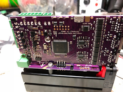
I had a batch of 50 PCBs made by PCBAStore for a very reasonable £47 per board. These kits were without the more bulky and expensive components. This blog post describes how to assemble one of the kits in to a working drive.
The main documentation (work in progress) is relevant to both the current and future versions of the drive. However due to the withdrawal from the market of the IRAM256 chip used by the board any future versions are likely to be physically different and assembled differently which is why this is a blog post and not a documentation section.
1) Test the board and flash the firmware.
There is no point assembling the board if it is a dud. The boards are supplied with the two halves linked and with a bridge that permits communications.
Before the boards are powered up they need to have C143 (22µF 6.3mm dia) installed. Most of the boards that I supply will have this already. Do not power up the boards without this component.
Ensure that the white stripe on the capacitor is adjacent to the corresponding stripe on the board silkscreen.
The board can then be powered up with 24V to both halves. There should be two green LEDs illuminated
This is a good time to flash the firmware. See the main documentation for instructions how to do this.
Once the firmware is flashed and the basic functionality of the board is assured the larger components can be added. C21 and C22 (270µF 400 / 450V) should be added first. Again make sure that the stripes line up as shown below. Trim the leads off short to ensure spacing from the IRAM module.
It is imperative that the screws have insulated washers. These are supplied with the kit. Their function is to retain isolation gaps between the screws and the board tracks.
The IRAM module is spaced from the PCB with special 3D printed standoffs. It is easier to fit these round the screws (M3 x 14mm) prior to intalling the IRAM256.
Screw the mounting screws in to the threaded holes on the heat-sink. A dab of heat-sink compound will not come amiss at this point.
Add a plain standoff and another screw. The slots in the extrusion are grooved to accept M3 screws, so this will get a decent grip.
The IRAM256 can now be soldered. Take care to ensure that solder flows all the way through to join the tracks on both sides of the board, as shown below. These are high-current connections and relying on the through-hole plating to link the board-sides is not a good idea.
The 3D printed fan-mounts can now be installed.
And the fan can be fitted. The 3D-printed parts ensure that the fan is at the right height for later. The lower screws seem able to make their own threads in the lower grooves of the heatsink.
The photo shows the fan fitted the wrong way round, it should blow-in not suck-out.

The right-angle header should now be fitted, in the orientation shown, and on the side of the board shown.
And the steady-bracket can be fitted with the self-tapping screw provided.
The vertical board is designed to sit hard down on the fan and on the connector block. In this position and with the capacitor bracket it is really quite strongly and rigidly supported. It is important to solder the header in-situ to achieve this.
Connect the fan wires and the drive is completed. There are two schools of thought on fan wire routing, some prefer the wires to start from the other corner and connect on the other side of the PCB.


Hi, its first time I hear about STMBL, and it looks super promising. Thank you for this.
ReplyDeleteHi, do you sell me a board?
ReplyDeleteSorry, I don't have any spare, and the IRAM module is now unobtainable.
DeleteA new design using a different power driver is in development (I believe, I am not directly involved) and then availability should improve.
Tks. Can you sell me without iram?
DeleteI don't have any spare populated boards. You can have your own boards made from the files at the github site fairly inexpensively. I paid $42 for 10 boards delivered from seeedstudio.com (note that you really want ENIG plating for easy placement of SMT parts, though HASL is much cheaper)
DeleteOnly board do you have?
DeleteWhich components did you have PCBA add and which did you do yourself? Obviously you did the large caps and the IRAM yourself, but any others?
ReplyDeleteJust the electrolytic caps and the IRAMS.
Delete(But given that there are no more IRAMS to be had, the question is moot)
I saw a couple people talking about the lower current versions or the A variant, do you know if that actually works?
DeleteHello
ReplyDeleteIs there an import for the PCBA store for your shopping cart?
I would like to order the boards just like you.
Many greetings
They made a batch for DMSci from the gitter.im chat a couple of weeks ago, probably a better bet. Are you Slayer1000 there?
Delete