I owe a huge debt of gratitude to http://www.brufnut.de/WORKSHOP/LUCAS/lucas.htm for lots of practical tips on how to do the job.
The autopsy of the old mag had given me good idea of how many primary turns there were, but I had to judge secondary largely by volume. I did at least measure the wire, and 39SWG (0.09mm) looked right, so I bought a reel from eBay.
The brufnut web site suggests 0.025mm polyester between the layers, but I couldn't find any. I did. however, find 30mm wide adhesive Kapton tape on eBay for £2.25 a roll. Kapton (polyimide) is amazing stuff. Strong, insulative, and a colour that screams "technical". It also has an exceptionally high temperature limit. So I decided to use that.
Given that the Kapton is thicker, but possibly better, I decided to put a layer of Kapton in between every second layer. That might be a mistake, time will tell.
The original pole-piece insulators seem to be the same red vulcanised fibre material as fibre sealing washers are made from. At first I struggled to find that (Yes, I know lots of other things work, but I wanted to end up with things looking the same, I even have a roll of cotton/bakelite tape for the final layer of the coil.) I eventually found out that it is popular as an interface layer between blades and handle scales in knife-making, and readily available from eBay and knifemaking specialists .
In a just-before-the-weekend panic I ended up ordering some Mica sheet from RS, and the vulcanised fibre from both eBay and english-handmade-knives on thursday afternoon hoping at least one would arrive by saturday. You will be unsurprised to learn that all three turned up on Friday.

The picture above shows the primary windings (0.7mm / 22 gauge, 4 layers so about 170 turns) which I wound by hand, and the new vulcanised fibre insulation. It's tough stuff, I don't mind having far too much, it will find uses.
My main hobby at the moment, despite appearances, isn't old motorbikes. I actually work on an open-source CNC machine tool controller project. It wasn't a huge amount of work to reconfigure my CNC lathe to be a coil-winder, it just took a very short G-code program which loops round in feed-per-rev mode and progressively reduces the width of the winding to avoid arcing to the pole pieces.
To facilitate stopping the process to add the inter-layer insulation I also added a small encoder to control spindle-override which ended up G-clamped to the tailstock handle.


The coil winder is fairly simple, but as every other example on t'internet glossed over the details, I will explain mine:
The spool sits at right angles to the first roller so that the feed angle stays the same. The position of the spool is adjustable on some T-slot extrusion to allow for different spool diameters. The spool spindle runs in skate bearings inside the adjusting block. The spool spindle is M12 threaded and includes one fixed cone. A second cone screws on to support the spool. The spindle and cones rotate as a unit inside the mounting block.
The wire passes to the first roller through a hole in a bit of plastic to stop the inertia of the spool pushing the wire off the roller, and to make it harder for it to miss the roller.
The first roller has angled sides, and a flat middle. The wire wraps round it twice, like a capstan or winch.
There is a brass plunger and adjustable spring bearing on the side of that pulley to control wire tension. The inertia of the spool is so high relative to the wire strength that it seemed like a bad idea to try to control tension at the spool.
The second roller is V-shaped and free-running and only guides the wire.

This is the final result, wrapped in Kapton and with a "staple" poking out (like the original) to solder the HT lead to. I went with 12,000 turns of 0.09mm wire. If I was doing it again I might use more, maybe 15,000, as the final resistance was less than I expected (3.2k). The spark isn't amazingly strong, but I am not convinced that there is much energy in the system to work with.
I actually tested the coil like this, but everyone says that a coil needs to be vacuum encapsulated to avoid a short life due to corona discharge, so I made a very simple vacuum box.
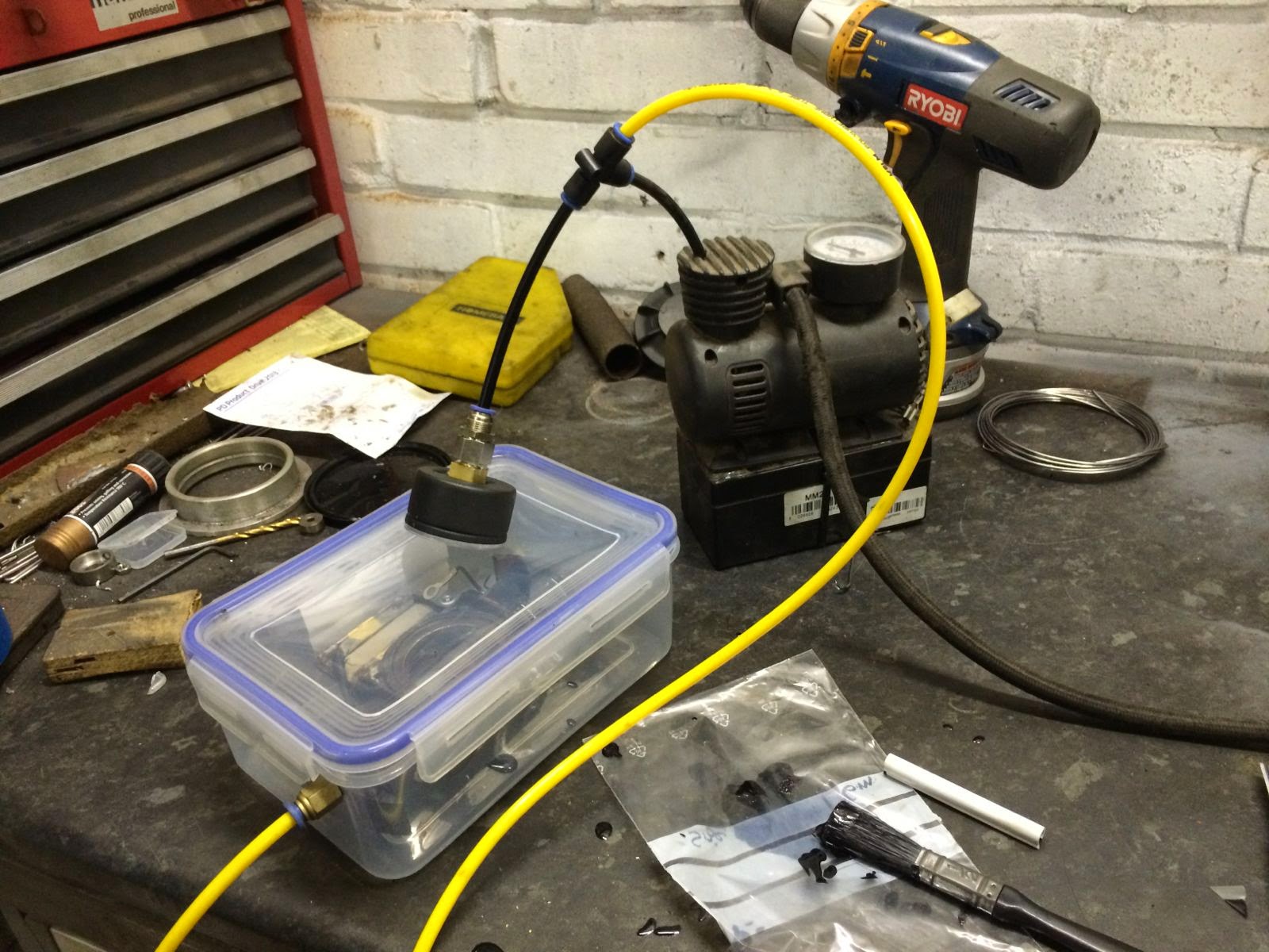
This uses a very cheap tyre inflator re-arranged to be a vacuum pump (this is actually a mod I made a while ago to use it to pump argon from my welder into the GasGas monoshock I was rebuilding). I recalibrated a pressure gauge to be an absolute pressure gauge (ie, I bent the Bourdon tube so it read 1 bar at ambient). The freezer box just about copes. It is worth mentioning that a perfect vacuum is only 1% more force on the vessel than a 99% vacuum. 1000x better vacuum isn't 1000x the crushing force.
In actuality I only get -0.9 bar with this setup, but it is enough to see bubbles in the epoxy and an oozing-in when the pressure is released.
I used the potting epoxy that comes in a divided plastic bag from Robnor resins. This is good stuff, and very convenient, and I strongly encourage you _not_ to use this. I really regretted it because I failed to note that it has a 2 hour pot life at 20C and takes 24 hours to cure. Fine in a potting box, really annoying when dripping round the outside of a coil. I ended up putting it back in the the lathe on a very slow speed while I got out my reflow-soldering oven. Which might look a lot like a cheap eBay toaster-oven.

This saved me from 3 hours of manually anti-drippping the coil, and the final result (prior to cosmetic old-school insulation wrapping, looks like this:

The eagle-eyed might spot that I added a safety gap, which as far as I can see the original didn't have.
Did it work? The video below answers that question. I did take the easy way out and have a commercial magneto rewinder re-magnetise the flywheel for me, which helped a lot too. (Salmons in Burnham)
Kickstarter
In the video I am using a collet chuck on the crankshaft. This isn't a long-term solution, clearly. In fact the Ner-a-Car has a kick starter, though I didn't have the spring or the curious split-washer and collar retainer.
Making springs is actually surprisingly easy. You basically just need to wrap some spring-wire round a former:

Making a spring this way has an element of pot-luck on the mandrel diameter. This one was too big, I got it right on the second attempt. I actually re-used the wire from the first attempt. It seems to work:

The coil sizes could me more consistent, I might adjust them when I re-fit them when the magneto goes back on. Also shown is the split-washer and collar arrangement. A circlip would work just as well, but I think that they were waiting to be invented in 1921.
Frame Alignment.
In the manner of Captain Black there are two schools of thought on whether motorcycle wheels should be coplanar. Unfortunately I belonged to the opposing school of thought to that evidenced by the bike. The causes are likely to be myriad: The chassis has been cut and welded, it as been dismantled and re-riveted, it might well have been crashed in its working life. By whatever cause, the chassis was notably not-straight.
To address this problem I converted my garage floor into a cheapskate Motoliner by the simple expedient of drilling some holes and inserting Rawlbolts and threaded rod.

Using a spirit level I set the cross-member at the steering head parallel to local gravity, then twisted the rear cross member (with the wheel out) to be coplanar.
I then fitted a dummy rear axle and used a jack to make the axle horizontal.

By clamping a billet of aluminium to the nearside rear stiffener I was able to get the rear frame member parallel to the frame using a ratchet strap, and I was also able to correct the frame spacing and centralise the rear wheel.
Similar efforts at the front made the suspension irons level, and made the axle swivel mounts more nearly aligned.
The frame is now ready for the engine and transmission.
No comments:
Post a Comment