
Not unexpectedly they came out a bit more than I had been quoted, but then I ended up making things rather thicker than during my initial enquiry. I said that the Z-box (on the top right) would be 6mm wall thickness and it ended up 20mm at the mounting face and 12mm elsewhere. It is actually quite a heavy lump (35 kg or so). You know you are lifting it.
Also in the picture are an apron casting, two bars to make into a gib strip (one is a spare), a toolpost mounting bracket and an X-drive cover (+ a spare, just in case). £350 all in from A J D Foundries.

The first task was to square the Z-box up, removing the pattern draught and making to finished size. The smallest dimension was just within the capability of my mill in vertical mode.

But it is lucky that I have a horizontal spindle for the other faces.

Even then, I needed some pretty hairy setups. It would have been bad to lose the vertical servo at this point.
With the casting all squared-up it just needed the housing making for the angular contact bearings. I was intending to do this on the undersized milling machine with my boring head, I even made a suitably long boring bar. But then as I was going to visit my parents for Christmas, and my dad has a Kearns S-type borer, I thought it made more sense to use that instead.
The Kearns is a machine pretty much dedicated to this sort of work, so made an unsurprisingly marvellous job of the task. However when I got the casting back to my workshop I found that my core box mould had too much paint in one area, and I did not have quite enough space around the drive sprocket, and had to do a bit of circular interpolation with a side-and-face cutter poked down the hole back on the Harrison.

Maybe not the clearest "action shot" ever, but it did the trick nicely.
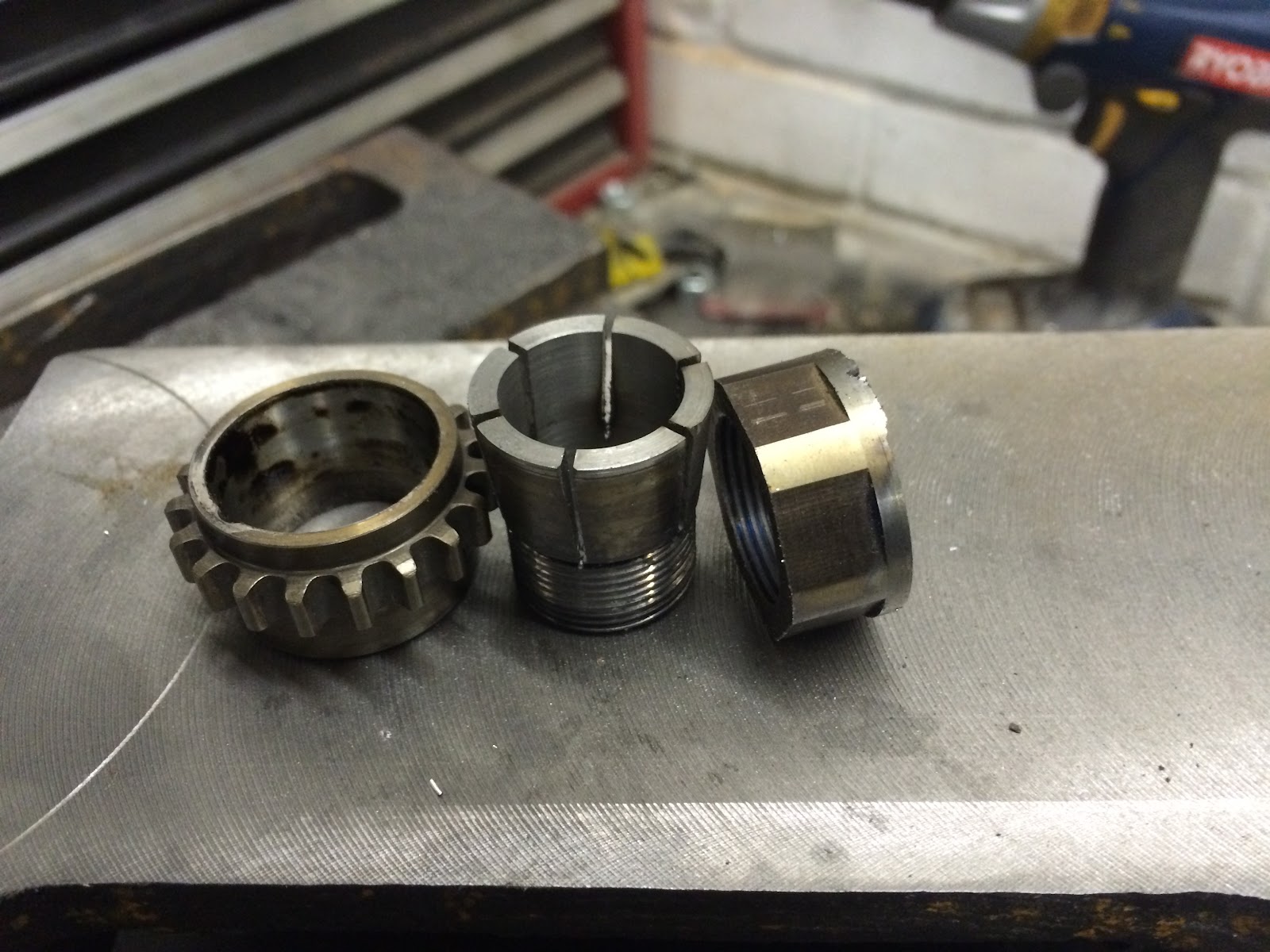
Access was also rather difficult to the motor flange mounting holes. My get-out-of-gaol-free card here tends to be a little ER16 collet extension that I have. It will hold a drill nicely and is a lot slimmer than a drill chuck.

The motor has a moderately large shaft, and the sprocket (a Yamaha R1 camchain sprocket) isn't very large, so I couldn't use a commercial Trantorque bush. But I could make my own, using the sprocket itself as the outer taper. I slitted the inner taper by hand with a Dremel wheel on the basis that no matter how scruffy it turned out, it would still work fine. Imagine my surprise when it didn't turn out at all scruffy.
There then followed a minor hiatus while I waited for some etch-primer to arrive, so I made a start on the toolpost casting. This is slightly lower than the original compound slide, and allows me to use 16mm tools.
In an attempt to get perfectly flat mating surfaces I invert-turned the part using my milling machine and a boring head. It would have been a natural job for a face-plate on the lathe, except that I don't have a face plate and the lathe that is big enough is in bits.

A quick lick of paint and some new curved T-nuts for the cross slide, and the toolpost is mounted. I made it eccentric because I can't quite get enough travel to turn the full 10" capacity of the lathe with a ball-nut in the saddle slot. So I can swing the toolpost about to reach further back, or to the left and right, as required. I imagine I will find one position and stick with it, but it never hurts to have options.

As I might have mentioned, I am using a second-hand cam-chain to drive the ballscrew. This is much too long in it's wild state, so needed to be shortened. I was worried that this might be very difficult with an inverted-tooth chain. Many seem to use all sorts of fancy rocking link pins. Luckily some experiments with a Dremel showed that this wasn't the case here. I made a little "anvil" with a hole in it that fits in the milling machine slots and was able to split and re-join the chain using nothing more elaborate than a specially-made pin-punch.

And here is the chain installed.

I am using chain rather than belt as the lathe headstock has a forced-lubrication system, and pumps oil from the feeds gearbox. I wanted to keep this, and exploit it. The larger of the holes in the bearing housing in the picture above is an oil-feed to the angular-contact bearings. I put in a diverter tray to catch the oil from the head drain, and it feeds from there to the angular contact bearings...

...and via copper pipes to the drive chain and the oil sight-glass. The nylon pipe is the oil suction pipe from the pump in the headstock.

The ballscrew fits into a taper held in the angular contact bearings and is held in place with a nut. I needed a lathe with a working threading gearbox, and also one with a 0.5mm pitch option for another experiment that I will only mention again if it works. This precluded the use of the Holbrook itself (which has no metric threading capability with the changewheels I have) so I took the ballscrew into London to the Motor Club garage. I have some CBN (Cubic Boron Nitride) inserts and these make turning ballscrews really quite easy:
With the taper and threads done, I could then fit the ballscrew and work out exactly how long it needed to be:

The bit of wood is a temporary expedient to keep foreign bodies and wildlife out of the headstock oil.
It would then have been a very simple job to shorten the screw and machine the journal for the end-steady bearing on the Holbrook. Or it would have been simple had the drivetrain not seized solid part way through the job. Clearly something is terribly amiss in the 2-speed box or the Variator and I imagine that will be the subject of the next update to this blog.
No comments:
Post a Comment