Luckily, as detailed in another previous installment I anticipated the problem and I have made a frame to allow me to jack the lathe up on to castors to move it about.
It actually took rather longer to make a space to move the lathe to than to push the (700kg) lathe across the garage, and I was left feeling pretty smug about my foresight.
The lathe manual seems proud of the fact that "The entire drivetrain is removable as a unit for easy servicing" which is indeed true. What they don't make such a big deal of is that the drivetrain on its baseplate weighs about 200kg and has about 1/2" of headroom. I eventually managed to extract it with the help of my Crowbar of Doom (which is useful for all sorts of machinery moving jobs and is a superb bit of equipment, all the shapes and angles are perfect).

The Kopp Variator actually freed-up as soon as I took the fan cover off and wiggled the motor fan, but I decided to have a look inside anyway. It also relieved me of any worries that the problem was actually with the 2-speed gearbox.
Getting the Variator across the workshop onto the bench was a struggle by myself. The manual says that with the motor flange (but not the motor) it weighs 75kg. I was left with a rising sense of panic as I was unsure I would make it to the bench, had nowhere else to put it down, and was wearing carpet slippers[1].
The Kopp manual says that you should dismantle from the output end. The Holbrook manual hints that they fitted the Variator back-to-front. I can confirm that in the Holbrook installation you want to take off the end cover nearest the speed adjusting worm shaft, in my case that was the motor end.
All fasteners on my Variator appeared to be metric. This incuded the tiny locking screws for the end-float adjusters.
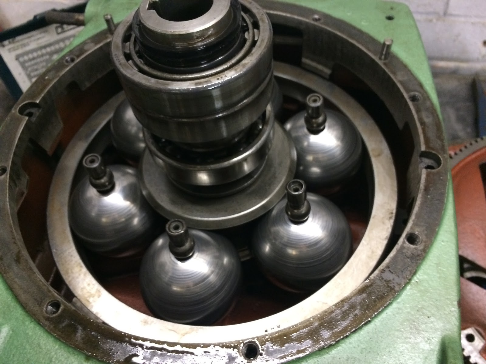
The Variator is rather clever. The speed control rotates an iris plate into which spherical rollers on the axles of 6 balls fit:

The ends of the axles run in tracks in the end housings So as the iris plate rotates the axles of the balls tilt one way or the other. In the horizontal position the gear ratio is 1:1, with the axles tilted all the way one way it is 3:1, and the other way is 1:3.

The main problem with my Variator had become clear before I removed it from the lathe. There was very much less oil than there should be in there. No more than half, possibly even less. Certainly when I took it apart everything seemed completely dry. Luckily all the friction surfaces seemed pretty much OK and the problem that I had had with it seizing appeared to be due to overheated oil turning to sticky laquer. (Perhaps it was the wrong oil, Allspeeds Ltd are very insistent that only one oil will do, Shell Morlina S2 BL10)
These are the balls as I found them. A tidy workplace and absolute cleanliness are paramount.

And here is one ball dismantled from the axle. I have not seen split-cage needle rollers before. Now I know that they exist I can think of all sorts of uses for them.

The picture above is also a good one to explain some details of how the system works.
The outer ring matches the ball diameter on the inside and floats on the balls. (It's an RHP part, I think it is the outer race of a spherical roller bearing). The two drive cones are not keyed in any way to the input or output shafts, instead they have a set of ramps and a roller-thrust bearing arrangement. There are matching ramps on the input and output shafts. So: Input torque causes the rollers to roll up the ramps, which pushes the cones inwards. The balls slide out a little until restrained by the outer ring, at which point the pressure increases until the output shaft starts to move. So there is only ever the right amount of pressure to drive the system.
It is important to have the end-float correctly adjusted for this mechanism to work properly. I found it better to back-out the end-float adjusters before final assembly, then adjust them afterwards. You just need to loosen the tiny locking grub-screw then use a pin-spanner to adjust the adjusting plugs until they are both in the same axial position relative to the end cover, there is no backlash/play between the shafts and the unit turns freely by hand.
I have ordered some special Variator oil to see if it does in fact work better with oil in it, even though I have actually decided that I won't be using the variator in my CNC conversion.
The 2-speed gearbox
I will. however, be using the 2-speed gearbox. This is electrically controlled so easy to integrate with CNC. Inside there are two clutches to engage either straight-through 1:1 gearing or the 6:1 ratio. Slightly oddly the reduction gears are 12:144 then 84:84 which violates normal design practice of having a "hunting tooth" so that over time every gear tooth sees every other gear tooth.
In the external cover lives another clutch that serves as a spindle brake. Unlike the other clutches this one is not easily disconnected, as the terminal nut is inside the case, and the wire passes through a gland.
On my lathe the brake had been disconnected, and I don't know it it was working. It certainly wasn't after I had extracted the drivetrain, as I forgot about the wire. When I looked inside the case the wire had pulled out of the eyelet. This was a minor problem until I tried to fit anew eyelet, and the terminal screw snapped as I tightened the nut.
So, I took the brake off to see what I could see.

The plates are on the left, these alternately mesh with the central hub (keyed to the gearbox shaft) and the outer dogs of the electromagnet (on the right). The plates are all ferromagnetic, and want to stick to each other when current flows.
This wasn't going to work very well unless I could make current flow, and the broken off screw had no electrical continuity to the magnet. (when the screw broke off it came with solder and a bit of wire.
I had some reason for optimism, though, as poking a multimeter probe down the hole did find an electrical connection.

After toying with a number of elegant solutions I decided to just solder a wire into the hole and keep adding solder until it found something to make contact with. The magnet windings are all encapsulated and mounted in a heavy-duty steel case.

Luckily this appears to have been a complete success. I will be inserting a knot in the cable inside the case and a bullet connector outside to avoid making the same mistake again in the future.
I have the parts on order to make a motor bracket to fit in place of the Variator for direct drive via a VFD. Then I will experiment to see if I want the Variator back.
[1] I exaggerate, I was wearing hiking boots, but only by accident.
With a 6:1 gearbox you might be perfectly happy without the variator
ReplyDelete